Standard 180° return bend
First of all, a standard return bend connects two compatible parallel tube paths through a defined radius.
Review specification details →
Copper return bends for coils and tube circuits
First of all, source a Copper U Bend by tube outside diameter, wall thickness, centreline radius, centre-to-centre spacing, leg length, end form and quantity.
Product overview
In addition, S K Metal supplies formed copper return bends for buyers who need repeatable connections between parallel tube paths.
Moreover, each component must match the tube OD, wall thickness, centreline radius, centre-to-centre spacing, leg lengths, end geometry and joining method. However, the description “U bend” does not define every dimension. Therefore, buyers should provide a drawing, approved sample or complete dimensional schedule before ordering.
See what to include in your U-bend enquiry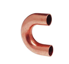
Types and configurations
First of all, confirm the required 180-degree return geometry. Then verify tube OD, wall, radius, centre spacing, legs and ends.
First of all, a standard return bend connects two compatible parallel tube paths through a defined radius.
Review specification details →In addition, extended straight legs can support the specified insertion, trimming or assembly requirement.
Discuss leg dimensions →However, a tighter centreline radius must remain compatible with tube wall, forming limits and system design.
Provide the radius requirement →Moreover, an expanded or swaged end must be defined by mating size, insertion depth and joining clearance.
Request dimensional review →Furthermore, coil enquiries should identify circuit spacing, tube dimensions and cleanliness requirements.
Discuss equipment requirements →Finally, drawing-based radii, spacing, leg lengths and end forms can be reviewed for project requirements.
Upload a dimensional drawing →Specification guide
Therefore, a complete specification helps prevent errors in tube size, return geometry, centre spacing, leg length and joining requirements.
Important: Do not select a return bend from OD alone. Therefore, the system designer should approve material, wall, radius, spacing, legs, ratings and joining procedure.
Applications
Because systems differ, the correct return bend depends on tube dimensions, circuit spacing, joining method and operating conditions.
For example, compatible return bends connect parallel tubes in an approved heat-exchanger circuit.
Moreover, specified U bends can join adjacent tube passes in compatible condenser assemblies.
In addition, approved return bends can support planned refrigerant flow through evaporator circuits.
Furthermore, equipment connections may need drawing-controlled radii, spacing and end dimensions.
However, pressure, medium, temperature and joining requirements must suit the exact cooling application.
Therefore, repeat components should be approved by drawing, sample, tolerance and inspection criteria.
Quality and documentation
Before ordering, define the OD, wall, radius, centre spacing, leg and end checks required for the exact Copper U Bend. In addition, designers can review the Copper Tube Handbook for general information about copper tube and joining practices.
Discuss your material requirement →Ordering checklist
For an accurate quotation, send the fitting schedule or drawing together with the complete tube and service specification.
First of all, state standard, close-radius, long-leg, expanded-end or drawing-based configuration.
Next, provide OD, wall, radius, centre spacing, overall height, leg lengths and tolerances.
Then list plain, expanded, swaged or other end forms, insertion depths and alignment.
In addition, state medium, pressure, temperature, joining method and equipment reference.
Finally, include pieces, sample approval, packaging, destination, schedule and documentation.
Frequently asked questions
In general, it creates a 180-degree return between compatible parallel tube paths. Its radius, spacing, legs and ends must match the approved circuit.
In addition, provide tube OD, wall, centreline radius, centre spacing, overall height, both leg lengths, end forms and tolerances.
Centre spacing describes the distance between the parallel tube centrelines. However, the exact relationship to radius depends on the approved bend geometry.
However, feasibility depends on tube size, wall, radius, leg dimensions, quantity and tooling. Therefore, submit a dimensional drawing or approved sample.
In general, the approved method depends on end geometry and equipment specification. Consequently, state brazing, soldering or another required method.
Yes, but availability varies by order. Therefore, list material, dimensional, inspection and traceability requirements before quotation.
Request a quotation
To begin, include tube OD, wall, radius, centre spacing, overall height, leg lengths, ends, service, quantity and delivery location. Afterward, S K Metal will review availability and quotation details.
Send your requirement